Tutorial: Intro to Unreal Engine Master Materials

Tutorial / 03 March 2023

In this post I aim to go over the basics of Master Materials in UE in as simple terms as possible. What they are, why we use them and how to make a very basic one. This is aimed at beginners.

1. What's a Master Material?

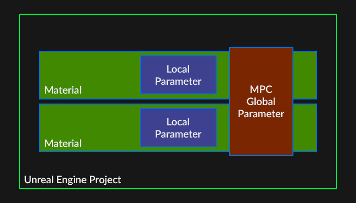
Master Materials are very similar to any other materials you create inside Unreal. They can range from being simple graphs with a couple of shader instructions and texture samples to gigantic, complex ones with multiple nested functions, parameters and parameter collections.
The main difference is in how Master Material inputs are parameterised. While regular materials use Static Values (textures, numbers [integers, floats, etc.] and so on) most if not all nodes in a Master Mat will be turned into Parameters (same but can be edited in a Material Instance).

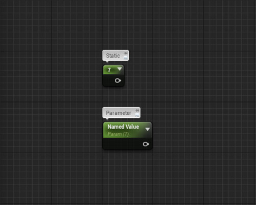
Static values are, well, static. They can only changed inside the Material Editor. Parameters on the other hand can be changed inside Material Instances. Allowing to create multiple varieties and thus different looking materials.

1.1 Material Instances

In simple terms a Material Instance is a much more user friendly child of the Master Mat it is instanced from. It inherits all the properties of the parent material and presents them in an easier to use form.
In a nutshell:


Material Instances do not need to be recompiled when updating a value or texture sample, the change is instant, in real time.

2. But why do we use Master Materials?

The main function of a Master Material is to provide other artists with easy to use Instances that still allow for maximum amount of flexibility and creative control. This can mean many different things depending on the artistic aims of the project. So your first job as the gal who's building the Master Material is to figure out what its requirements are. Can't build a house if you don't know how many rooms and floors it needs.

Master Materials serve as a SPOT (Single Point of Truth) from which all child Instances inherit all their properties. This is especially useful when updating or debuging your Material Graph. The disadvantage here is the time it can take to then recompile all the Instances too, it can take anything from less than a minute to over an hour depending on the size and complexity of your project.

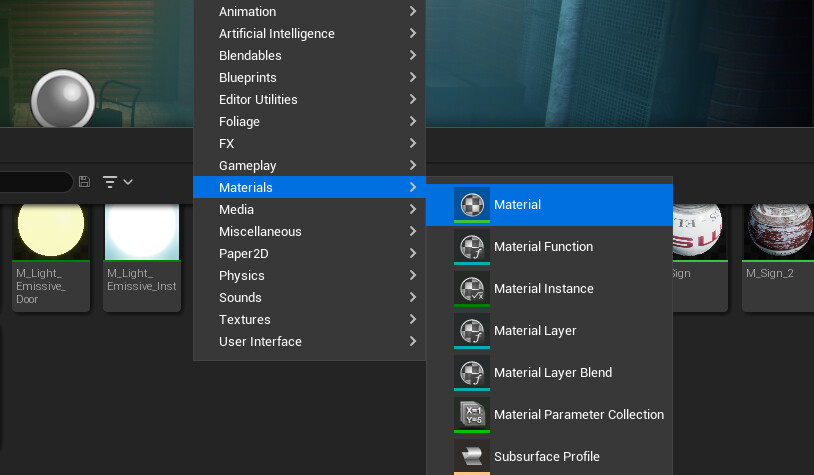
3. Hello World - My first Master Material

For my first Master Material I want the following features:

  • Use textures or flat value for Albedo

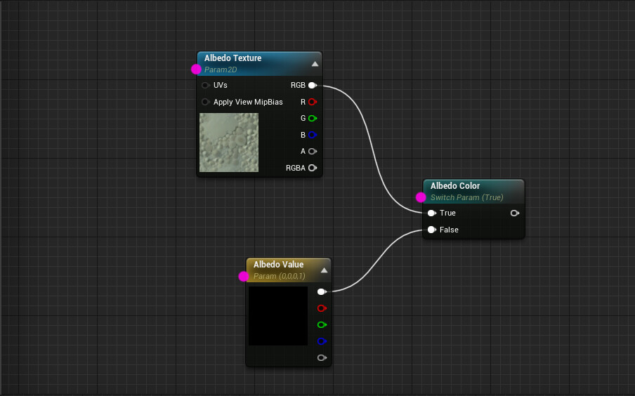
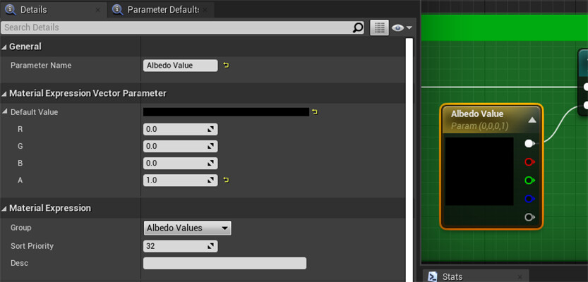
Note that every node here is a parameter. Albedo Texture is a Param2D, Albedo Value is a Vecto4 Param[0,0,0,1] and so is the Static Switch Param (Boolean: True or False). Each one of those is editable in a Material Instance derived from this Master Material.

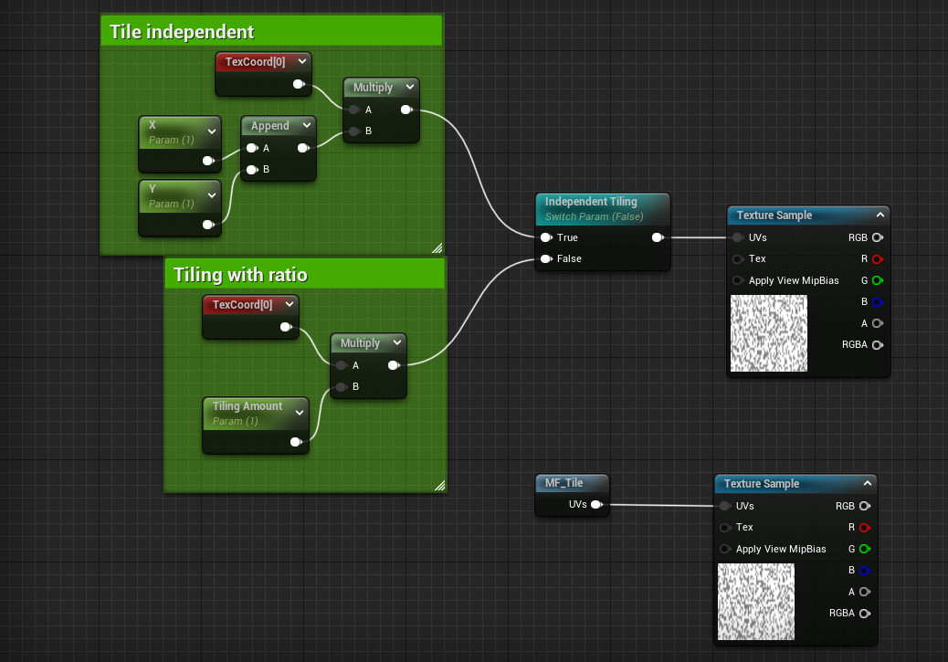
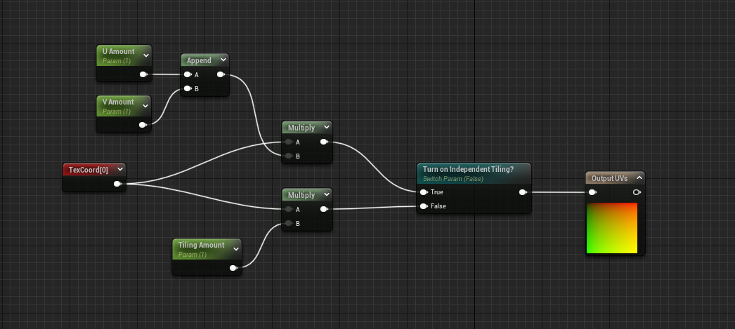
  • Be able to tile my material, both with ratio or independantly in X and Y coordinates.

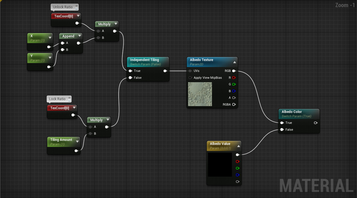
Some nodes cannot be turned into parameters. Neither TexCoord nor Multiply nor Append can be parametrised. But that isn't a problem. For locked ratio tiling I multiply my TexCoord by the Tiling Amount Parameter. For independent tiling I do the same thing but Append the X and Y values together first (Append works like this; 1 appended to 1 gives us [1,1], a Vector2). If this is confusing, remember that Texture Coordinates are represented by U and V values (Vector2). UV Unwrapping anyone?

  • Be able to use either Channel Packed Texture or independent grayscale ones.

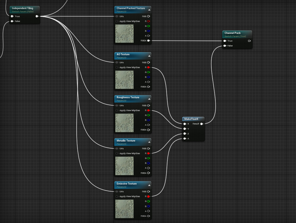
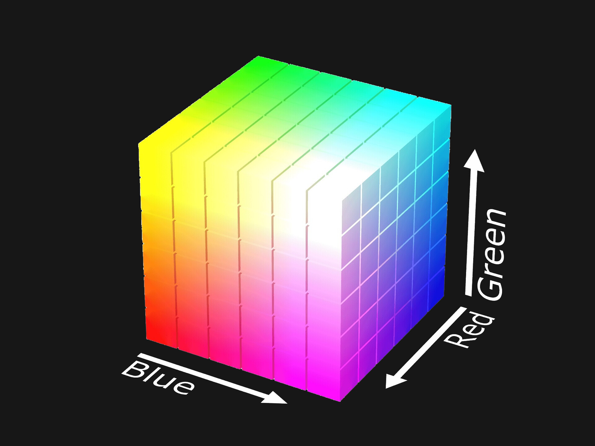
Alongside a Channel Packed Texture I use 4 Texture Param2D nodes here, one for each type of map. I put them together into a Float4 [X,Y,Z,A] using the MakeFloat4 (X,Y,Z,A here can correspond to R,G,B,A) node which I feed into the Channel Pack StaticSwitch Param. If set to False it'll hide the Channel Packed Texture Param2D and use the grayscale ones instead.

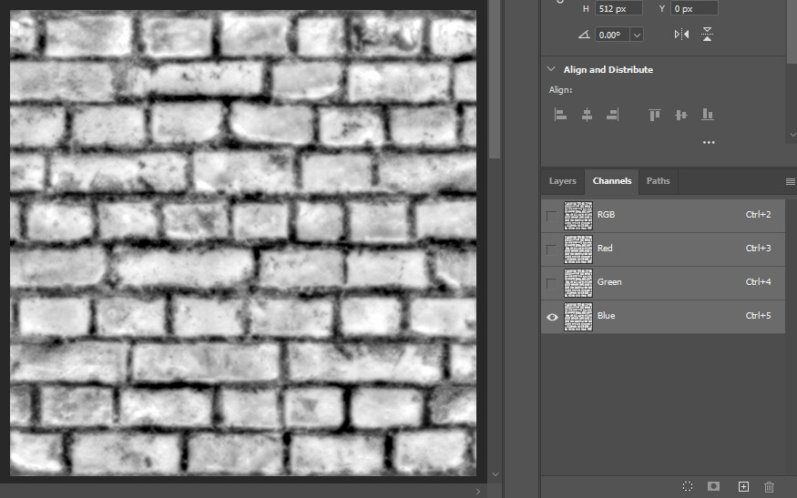
Very useful piece of information about black and white images, every channel contains exactly the same value. Why is it useful? Because the MakeFloat4 node only takes single values, if I tried to plug RGB (Float3) or RGBA (Float4) outputs from the Texture Param2D it would not compile. So I'm using the Red channel instead but any other will do (excluding Alpha which is commonly blank unless otherwise authored).

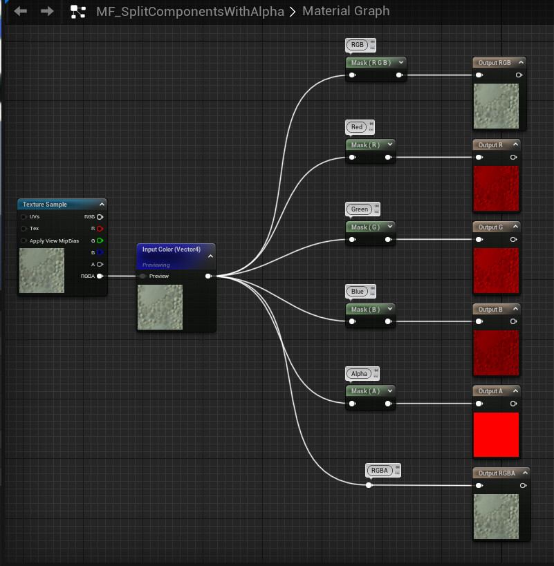
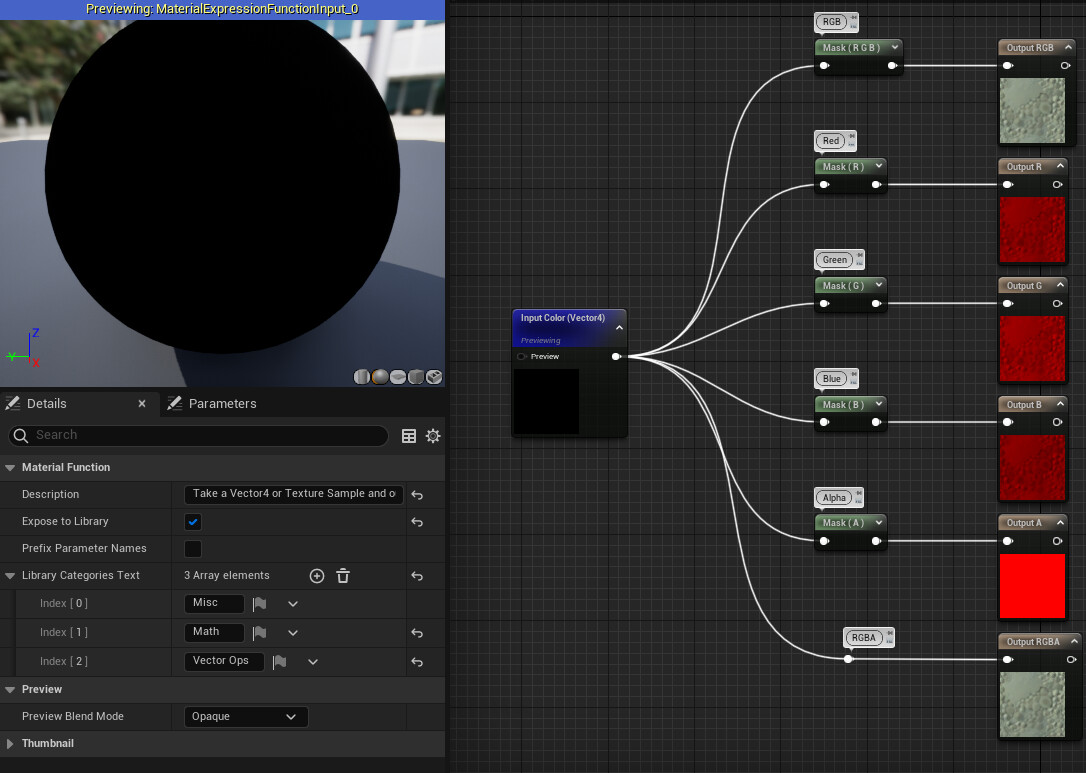
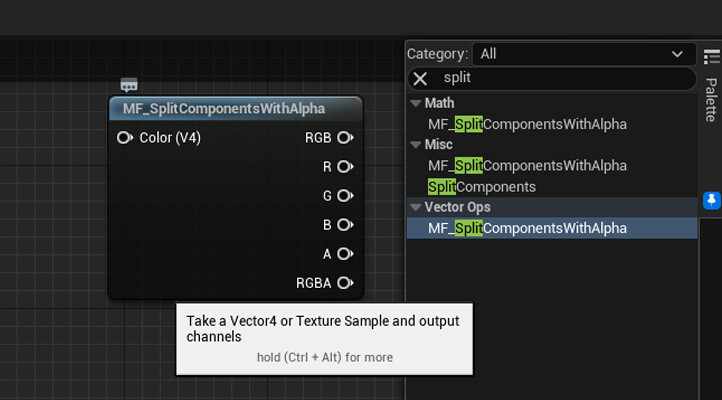
  • Be able to split the Vector4 from the previous operation back into individual channels which I can then plug into texture inputs.

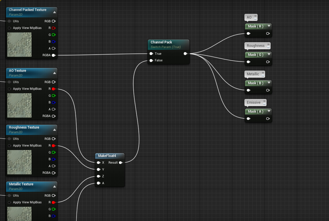
One way or another I ended up with a Channel Packed texture of sorts, which I now need to split back into individual channels as the StaticSwitch doesn't do it natively. I use 4 ComponentMask nodes, which allows me to choose which colour channel (or channels) it outputs.

! INTERMISSION !

Like with most things for Game Artists, there are multiple different ways to solve a problem. This is the perfect opportunity to illustrate that. Because there's another way implement the last two steps in our Master Material creation.

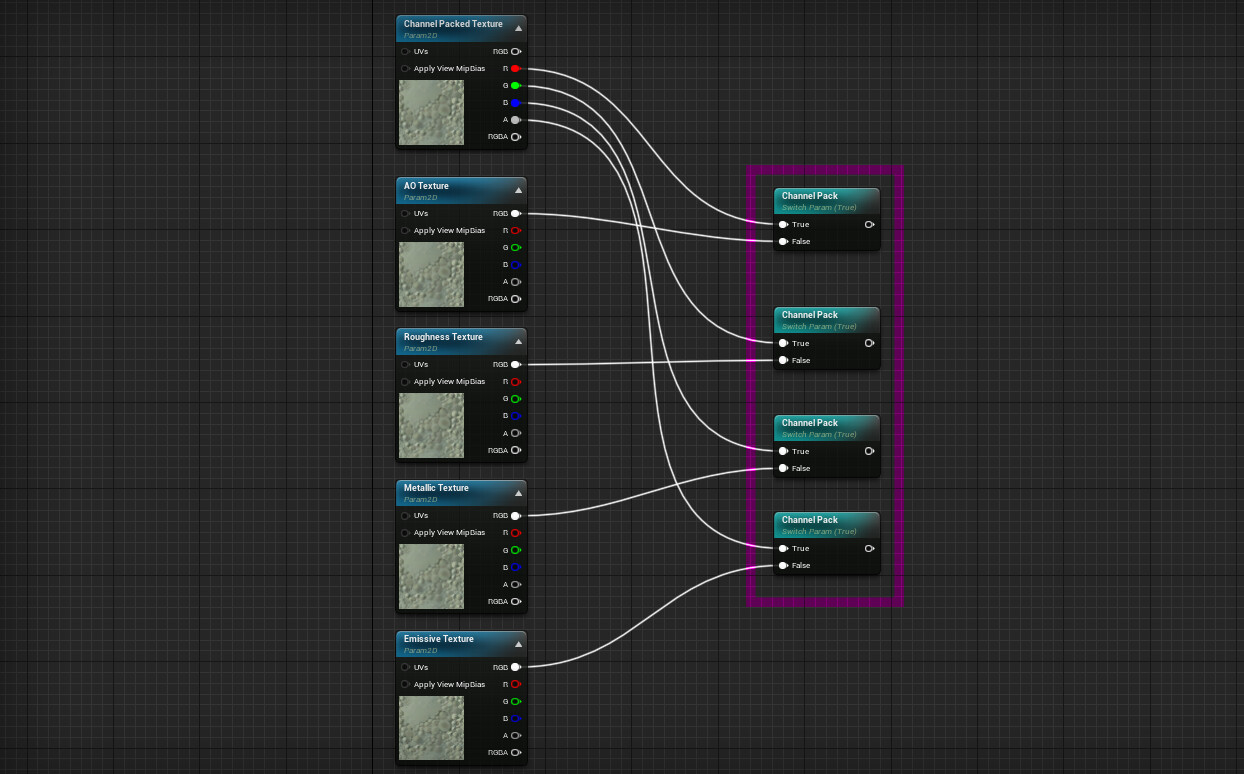
You see Parameters with the same name and type are counted as one and the same. This is represented visually by the nodes changing colour ever so slightly. Above I take advantage of that by using the Channel Pack parameter 4 times. One for each texture channel. I plug individual channels from my Channel Packed Texture into the True value of each Static Switch Param and individual maps into False (Optimally I always want to use one channel for grayscale maps, above setup will cause an ignorable warning in Material Instances but will still compile and work fine).

This results in a cleaner implementation of the same requirement while using fewer shader functions to achieve it.

! END INTERMISSION !

  • Be able to colour my emissive and adjust its intensity

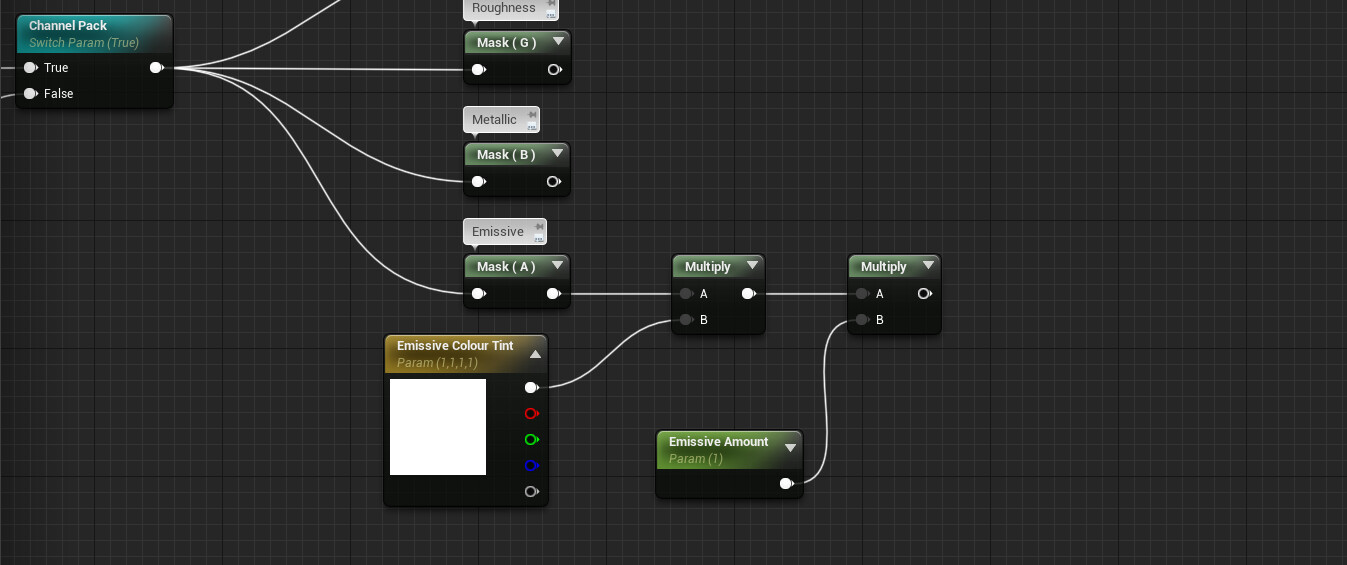
Nothing you haven't seen before, I use the Vector4 to tint my grayscale emissive then I multiply it by the Emissive Amount parameter to adjust intensity. Want to know why Multiply and Divide work differently inside Unreal Material Editor?

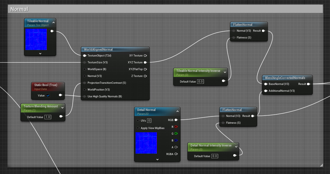
I also added a Normal Map Texture Param2D for bump information, it's linked to a StaticSwitch Param that will use a flat normal map if set to False. You can hopefully visualise how that looks now (flat normal in UE can be represented by a Vector3 [0,0,1]).

4. Finishing Touches

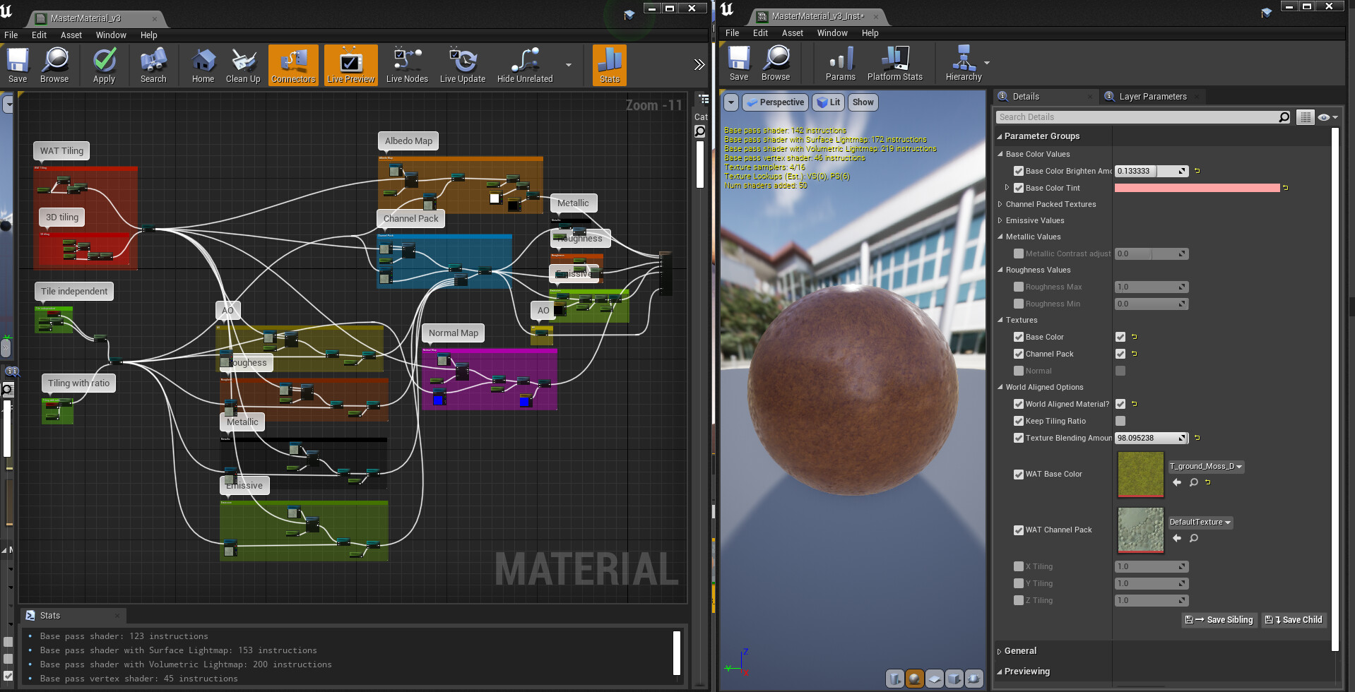
I think that's about it for our first Master Material! Here's how it looks:

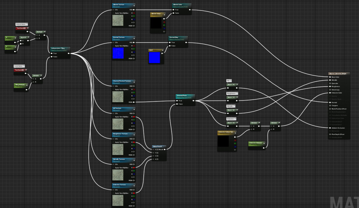
It's a bit of a mess and not the most readable. Which is fantastic, because I need to talk about Comments, Reroute Nodes and Parameter Groups. So let's get started.

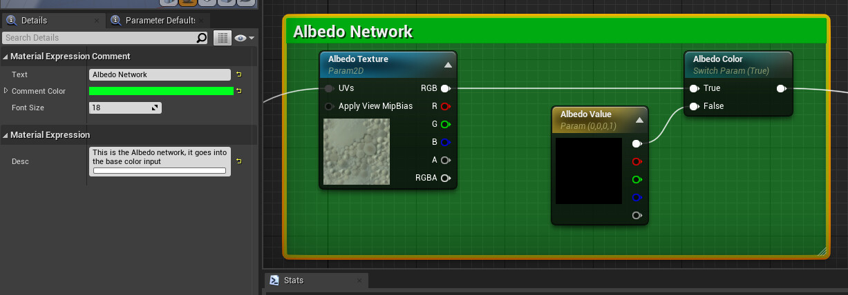
Comments allow us to frame nodes into neat boxes that you can name and change the colour and size of. Simply select the nodes you want to include and press the C key. Encompassed nodes will stay inside even when the comment is moved.

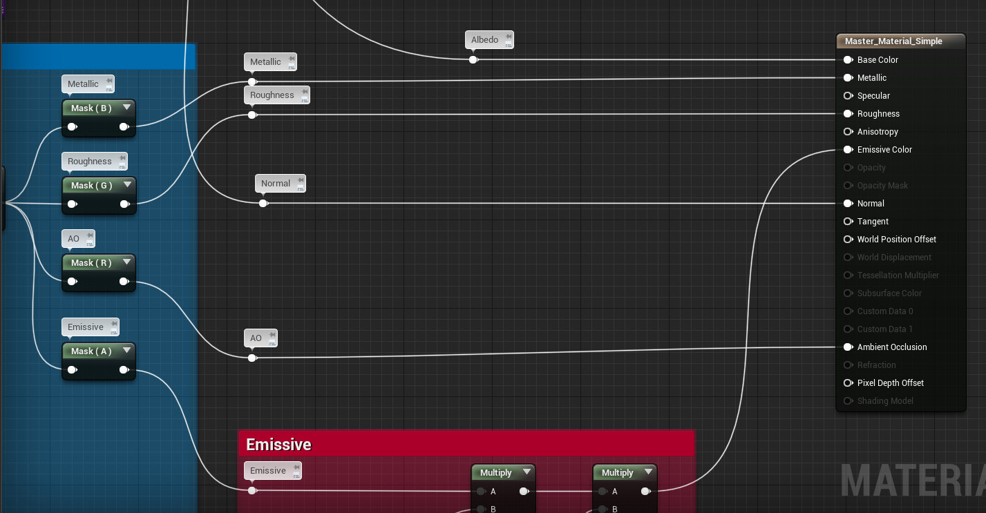
Reroute Nodes are great for organising our spaghetti into more structured noodles. Simply double click at any point on your line and a dot Reroute Node will appear, it can be given a description. It also functions like any other output and can be connected to multiple inputs.  


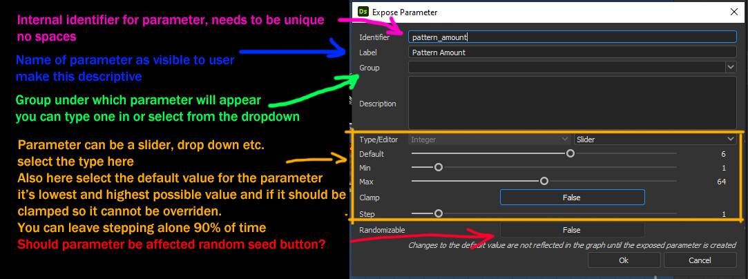
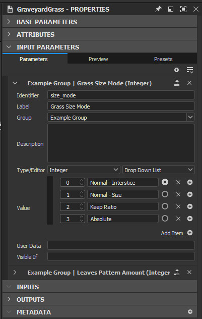
You already know parameters can and should be named (something descriptive!), they can also be grouped together and ordered. The Group dropdown allows you to select group under which your parameter will appear (you can also just type in a new group name here). Sort Priority lets you order your parameters, lower values will appear higher on the list in a Material Instance.

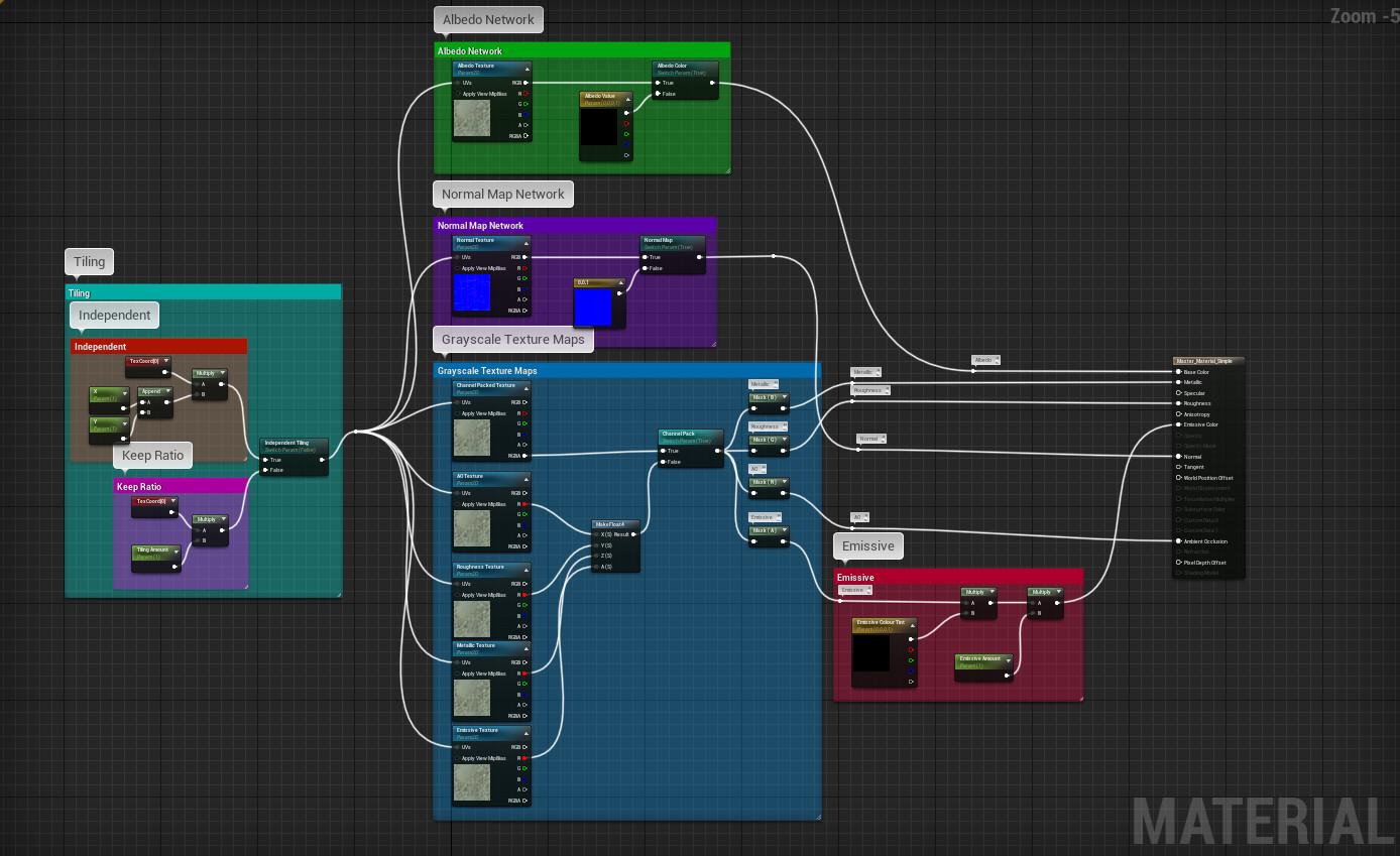
Taking my own advice makes things look much more readable.

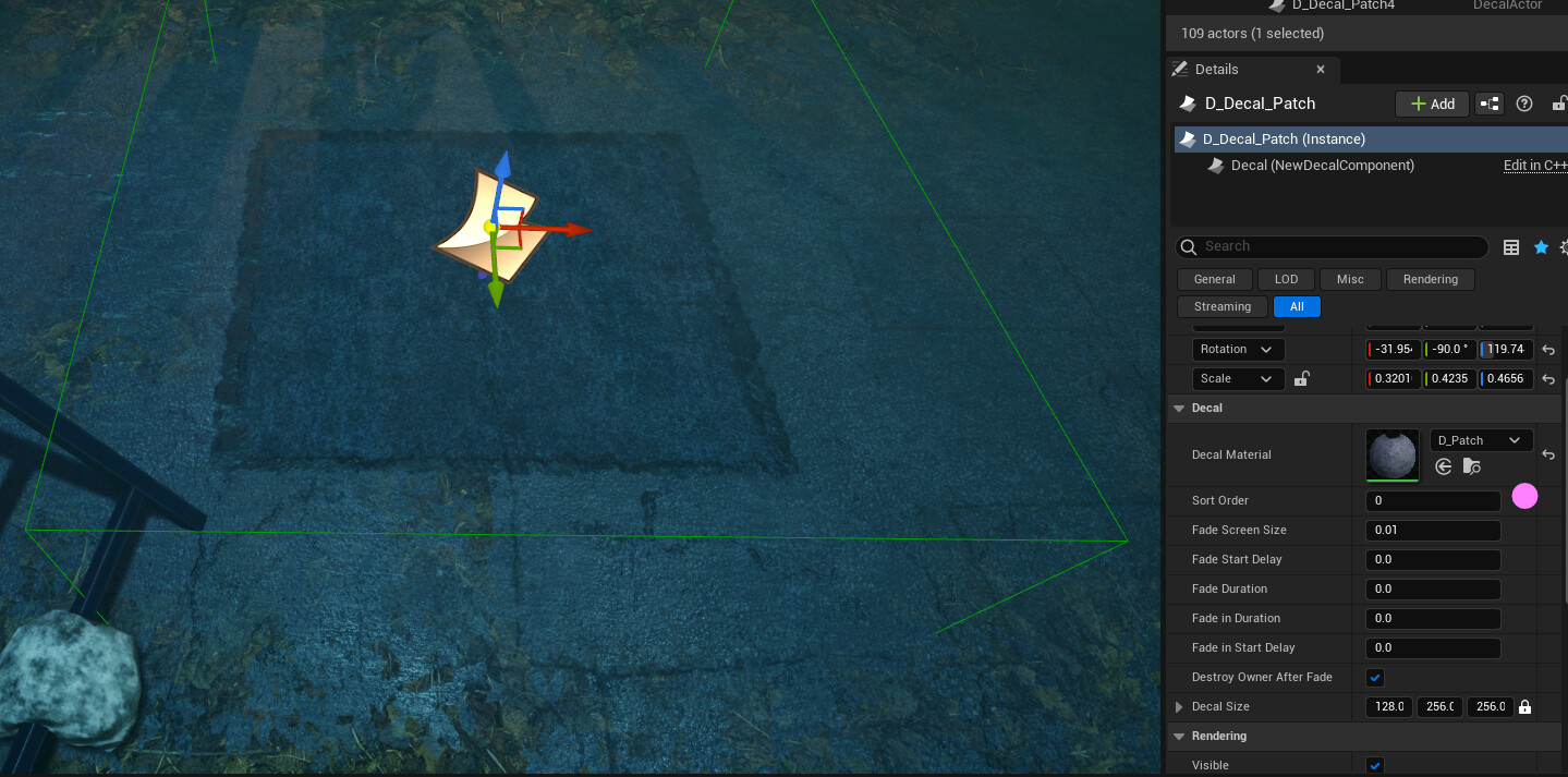
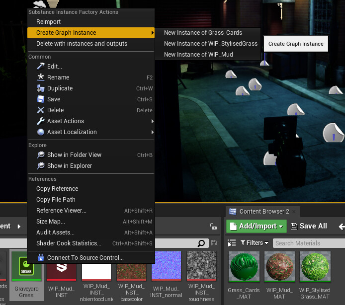
Now lets have a look at a Material Instance made from our new Master Material. To create one simply right click on your Master Material and select Create Material Instance. Remember to follow good naming conventions (MI_Name)!


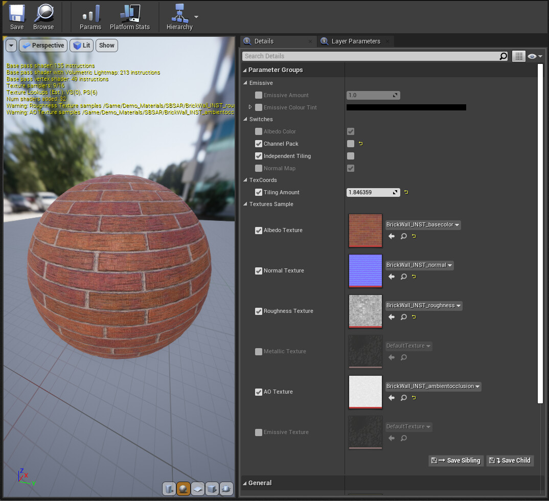
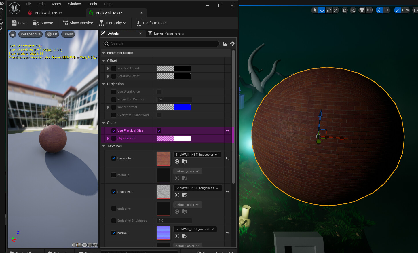
Nice, simple and readable.

And that is all for Master Materials 101. As said, this is a basic overview to get you started.

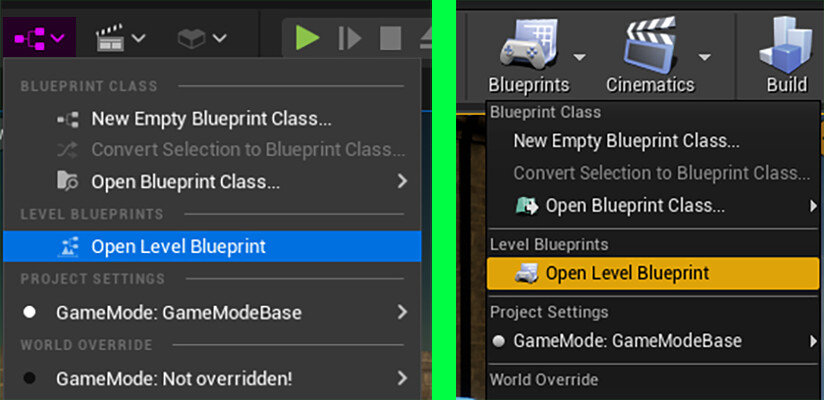
Creating and Using Material Instances
UE4 - Creating Master Materials

Addendum: High-Level Shader Language

HLSL was developed by Microsoft for Direct3D 9's API sometime around 2002 (GLSL is its analogue for OpenGL). If you're one of my current students, your parents were very excited to welcome you to the world around that time.You don't need to know anything about HLSL other than maybe being aware that ALL shaders, material nodes and whole materials (including every possible permutation) are writen entirely in HLSL in Unreal Engine. The Material Editor is just a convenient GUI we use.

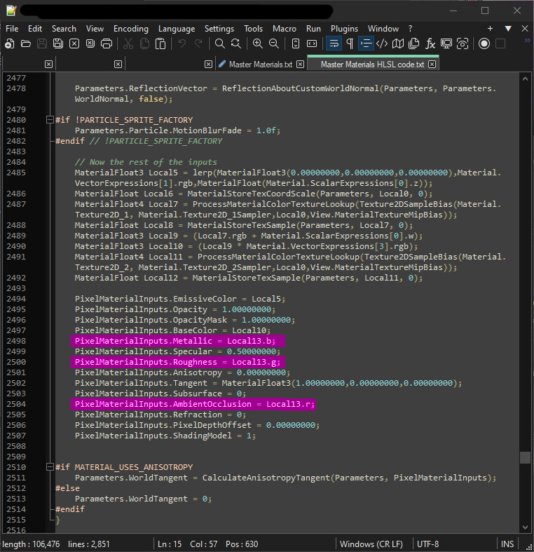
Here's a sample of HLSL from one of my Master Materials. Highlighted in pink are three lines of code responsible from taking a texture sample channel outputs and connecting them to appropriate inputs of the Pixel Shader. In this case Blue to Metallic, Green to Roughness and Red to Ambient Occlusion.

Full code can be found here.

HLSL is based on C programming language, which is why you'll sometimes see HLSL refered to as Cg (C for Graphics).

Crypt Project: Update 01

Work In Progress / 13 May 2023

It's been some time since I worked on this scene. Since my last post I played a lot of Diablo 2 Ressurected which inspired my change in direction.

I focused on getting the main two modular sets finished to a standard I'm happy with. Figuring out a good workflow here was a bit trickly. Since I already had tileable textures I wanted to use but also had quite a lot of normal information from the high to low poly bake I settled for a hybrid solution.

While the tileables use world aligned, the baked detail used UV channel 0. Then I blend them together. The final result works very well if not for some stretching which I still need to figure out later. Unique, non-repeating elements are unwrapped onto their own sheet and use a separate material. I've given myself quite a lof ot control here. 

One mistake I made earlier was not making my normal maps with iso view in mind. They ended up nearly invisible from a distance so I had to go out of my way to make them more visible. Here's how the crypt set looks with some fairly OTT normal maps.

Some areas could still be adjusted to make for better looking result. I need to push some base value to achieve more legible results. But I'm fairly pleased with the results for a first authoring pass. 

Next I'm going to continue replacing blockout meshes with more finalised assets. I also need to figure out how to fix the annoying normals issue on the top of the crypt.

Tutorial: Intro to Deferred Decals in Unreal Engine + Transparency and ID Mask in Substance 3D

Tutorial / 13 March 2023

This is an updated version of a previous tutorial which sucked ;)

Today I'm going to talk about working with Deferred Decals in Unreal Engine. But first I will run through my Maya (and 3ds Max) through Substance 3D (Painter and Designer) to Unreal Engine authoring workflow. This is a beginner level tutorial.

1. What is a Deferred Decal?

Deferred Decals (or just Decals, which is what I will be calling them from now on) are Materials that are projected onto meshes in your level, including Static Meshes and Skeletal Meshes. Decals are NOT meshes but rather materials placed on top of a mesh (or multiple meshes) using Planar Projection (flat projection in a single direction) helpfully indicated by a blue arrow just under the decal icon. The green, transparent Decal Bounding Box is the container inside of which projection happens.

Decals are best used for breaking up repeating textures and geometry, making your scene feel unique and more detailed. This could be scattered leaves, a patch of asphalt or cracks in a wall. Most decals use transparency, which creates the illusion of a unique shape and helps blend it into the environment seamlessly. We'll look at how to work with transparency in just a minute.

1.1 Considerations and limitations of Decals

Multiple Decals can be placed in your scene at once without impacting performance. However more complex Decal Materials may eventually start causing performance dropoff, especially close up when they take up significant amount of Screen Space (Screen Space is what you see on the screen or the display area available on your monitor, TV or any other form of display). Decals are best (but not exclusively) used on fairly flat surfaces, as more complex surfaces can result in stretching artifacts.

2. Authoring my first Decal.

I'm going to be making a manhole cover:

2.1 Creating Material ID Masks.

I use the standard Subdiv Modelling workflow in Maya to make the high poly of my manhole cover (check out the linked Polycount Wiki article to learn about Subdiv Modelling). I identified two types of materials I want to use, metal and concrete.

In Maya's Hypershade I create 2 Surface Shaders (I use Lambert but any other will do), Red for Metal and Blue for Concrete. I apply those to the appropriate geometry by selecting faces and from the right click menu selecting Asign Existing Material and then... chosing one!

In 3ds Max's Slate Material Editor I create a Multi/Sub-Object and plug 2 Shaders with the same colours as above. I select my manhole, then right click the Multi/Sub-Object and Asign Material to Selection.  For this to work correctly I have to set Material IDs for each surface type by selecting the geoemetry and typing in an ID number. See the pink dot in the image below?

As an aside, I can use the Select ID button to quickly select all faces asigned to the same ID and inside the Unwrap UV modifier the All IDs dropdown lets me display only the UVs with that particular ID number.

I also need a low poly mesh to bake my geoemetry on. Simple, square plane will do, it should already be UV unwrapped by default. This is used only for baking the high poly information. Decals are NOT meshes after all.

2.2 Substance 3D Painter material setup.

By default Painter uses an opaque pbr-metal-rough shader. When I create my new file using the low poly plane (Unreal Engine 4 starting assets Template) I first have to go into Shader Settings and change it to pbr-metal-rough-with-alpha-test (or alpha-blending if parts of my decal were to be semi translucent). Next in Texture Set Settings I add an Opacity channel through the + button.

The Unreal Engine 4 Template in Painter will put the Opacity texture into the alpha channel of my base color texture. Next, I Bake Mesh Maps. From the list I select ID and change the Color Source to Material Color. I can choose to bake an Opacity map here too.

Now I can add Mask with color selection to any layer or folder and colour pick my material IDs. In my layers I now also have a grayscale Opacity Channel (op) allowing me to mask visible geometry. The rest of my Painter workflow is out of scope of this tutorial.

2.3 Substance 3D Designer material setup.

In a new Metallic Roughness graph I add an Output, set its Identifier and Lablel as Opacity and it's Group as Material. I plug a white Uniform Color into it for now, then right click it and click View in 3D View and then Opacity.

Back in the Explorer, I right-click my Package -> Link -> 3d Scene. I navigate to the high and low poly meshes for my manhole cover (which I exported as separate FBX files before) and open them. Designer puts them into a Resources folder inside the package.

I right click my low poly and choose Bake Model information. In the baker window under Setup High Definition Meshes I select Add high definition model -> From Resources... and select my high poly.
In Baker default values I change Default Format to .tga (I could also increase Default Anti Aliasing for cleaner edges at the cost of longer baking time). From Baker render list dropdown I select Color Map from Mesh and change Color Source to Material Color.
Next I add an Opacity Mask from Mesh and then other maps I think I'll need. Last I change my Output to Embedded (into the current designer package) and click Start Render.

Baked maps are held in the Resources folder. I click and drag them into my graph. Color to Mask is the node that lets me use my Color Map for material ID masking.

I can use a RGBA Merge node to channel pack my Opacity with other grayscale textures or Alpha Merge node to put the Opacity mask into the Alpha channel of my Base Color Output (which Painter does by default as mentioned earlier). The rest of my Designer workflow is out of scope of this tutorial.

My Decal:

3. Unreal Engine setup.

I start by importing my .tga textures into Unreal Engine and setting them up for correct Compression Settings (I set my linear maps to Masks compression). Time to create my Material. As a quick recap; decals are simply materials projected onto level geometry. The basic setup is really quite simple.

I right click into my Content Browser and go to Materials (Materials & Textures in UE4) -> Material. I name it D_Manhole then go into its Material Graph.

I add in my textures and click on any empty space in the Graph to bring up the Material Details. I change the Material Domain to Deferred Decal and Blend Mode to Translucent. In Unreal Engine 4 I also need to change my Decal Blend Mode to DBuffer Translucent Color,Normal,Roughness.

At last, I connect my textures to the appropriate inputs, save my materials and it's done!

3.1 Placing a decal in my scene.

Decal Materials can simply be pulled from the Content Browser into my scene. They can be transformed (rotated, scaled, moved) just like any other asset in the level.

If I happen to have multiple decals stacked on top of each other, I can select the one and in its Details under the Decal pane change the Sort Order (lower values will appear higher in the stack).

If I have a mesh in my scene I don't want receiving decals (maybe it causes nasty looking streatching?), I can select the mesh and in its Details, under Rendering  Advanced find Receives Decals checkbox and untick it. Now this mesh will never receive any decals.

4. Conclusion.

This concludes a brief(ish) introduction to authoring Decals for Unreal Engine. Fantastic resource for game artists that will push your work to the next level. Now I think about it, you can use this workflow for pretty much every engine that implements decals in a similar way...

Tutorial: Intro to Unreal Engine Material Parameter Collections

Tutorial / 11 March 2023

In this short tutorial we will have a look at Material Parameter Collections, what they are and how to use them. Material Parameter Collections are a powerful tool for artists.

1. What are Material Parameter Collections?

Material Parameter Collection or MPC (which is how I will refer to them from now on) is a unique type of Unreal Engine asset that allows you to store multiple Scalar (single float value) and Vector4 (R,G,B,A) Parameters globally. What do I mean by that? In short, there are two ways to create (or "declare") parameters (or "variables"). Locally, inside of a material or Globally, inside the UE project you are working in. Local parameters can only be access inside a Material and its Instances. Global parameters can be accessed anywhere from within the project.

1.1 But why is that useful?

Inside of the Unreal Material Editor you can find a node called CollectionParameter which allows access to a parameter stored inside of a MPC (more on that later). As many materials as you like can access this same parameter this way at the same time. When this parameter is changed, all the materials that access it will also change accordingly. Because they all access the same parameter.


For example the amount of desaturation on all materials in your scene, controlled by a parameter inside a MPC.

2. Creating my first MPC.

For this tutorial I will be creating a Scalar Parameter to desaturate my scene and a Vector Parameter to control colour tinting some emissives. I will manipulate those Global Parameters inside the Level Blueprint

Lets get started!

I right click inside the Content Browser and go to Materials (Materials & Textures in UE4) -> Material Parameter Collection. I'm calling mine MPC_Colours (MPC_ is the common naming convention).

I open the MPC and am greeted with a simple menu with two Arrays; Scalar Parameters(Float) and Vector Parameters (Vector4) .Currently no other types are available. I click + next to the Scalar array and then expand the newly created param at Index [0]. Inside I find a Default Value field and Parameter Name input. I repeat this for Vector array except the default value is a Color Picker which I can further expand for individual numeric values.

I input my names and set default values of 0.0 and White(1,1,1,1) then Save. Well done me! Just made my first MPC. I'm sure Epic will be in touch to offer me a lead tech artist position shortly.

One MPC can contain 1024 of each type of parameter.

2.1 Implementing my MPC in a simple Material.

I creat a new material, throw in some textures and then in Palette I search for CollectionParameter which I pull into my graph. Inside it I select my MPC from the Collection dropdown, then select my Desaturation_Amount from the Parameter Name dropdown. It looks like this.

Last I find a Desaturation node, connect my Base Color sample at the top and the CollectionParameter (now conveniently named "Desaturation_Amount") to the Fraction input. This is what I end up with.

Take note that you cannot change the value of Desaturation_Amount inside the material or its instances. But you can perform operations on it. For example by multiplying it by a Local (one made inside the material) parameter.

2.2 Changing the value of Desaturation_Amount.

I want to be able to change my Desaturation_Amount whenever I press and hold the Spacebar. To do this using my Global Parameter I go into Level Blueprint.

First I add a Set Scalar Parameter Value node (you want the material collection instance one specifically), from Collection dropdown I select MPC_ Colours and from Parameter Name Desaturation_Amount. Next I add a new Float Variable called Desaturate and pull it into the graph as a Get. Which I then connect to the Parameter Value on my Set Scalar Parameter Value node. Then once again I pull Desaturate into the graph as a Set, which I then duplicate. First Set has a value is 1.0, second a value of 0.0. I connect the Exec outputs of both to the Exec input of my Set Scalar Parameter Value. Lastly I add a Space Bar node to my graph, connecting its Pressed Exec to Set Desaturate with value 1.0 and the Released Exec to the one with value of 0.0.

It looks like this:

Now when I play my level and press and hold the space bar, all materials which use the Desaturation_Amount function I made will go grayscale. I took the liberty of applying that logic to a number of materials in my scene.

Notice how desaturation only affects the materials and not the red light in the corner. MATERIAL Parameter Collection. 

2.3 Using the Vector Parameter.

I want to use my Colour_Tint param from MPC_Colours to make some constantly colour shifting emissive lights. I also want to have multiple instances that start from different colours to show how that will be affected by my MPC param.

First I make my Material, using Colour_Tint in the CollectionParameter this time. I use a SplitComponents node here to compress my Colour_Tint (Vector4) down to a Vector3 (R,G,B). It ends up looking like this:

I make 3 Instances with different base emissive colours and apply each to 4 spheres I have in my scene.

Now back to the Level Blueprint. I add a Set Vector Parameter Value (the material instance one) and select my MPC_Colours Collection and Colour_Tint Parameter Name. I create a new Linear Color Variable called Colour_Tint pull it into the graph as a Get and connect it to Parameter Value input. I pull it again as a Set and connect its Exec output to the Set Vector node Exec input. I add a Timeline node and name it Colour Tint. Double click that and add a Vector Track and create a couple of keys for each colour. It looks like this:

Creating and editing Timelines is out of scope of this tutorial but you can learn more here:

Back in the Event Graph I connect the new Colour Tint Vector output (orange) to Set Colour Tint. Node that converts Vector to Linear Colour is added automatically (I could have also used linear colour in the first place). Then connect the Exec pins together. Last I add an Event BeginPlay node and connect it to the Play Exec input of the timeline. This way the Colour_Tint will start shifting over the timeline when I begin playing my scene. My graph looks like this:


Here's a gif of my light spheres in action:

3. Conclusion

This concludes the introduction to Material Parameter Collections. An incredibly powerful but easy to use Material Asset Class.

There are some limitation to keep in mind when working with MPC. They can only contain 1024 of each type of parameter. Modifying the number of parameters in a collection causes a shader recompile for each material that references it. Material can only reference up to 2 MPCs (but unlimited number of parameters from them).

And most importantly, renaming a parameter will break any Blueprints that use it until it is reasigned by hand.

Additional Resources:

I almost forgot! Sequencer has a MPC track that can be used to animate your parameters. Read more about this straightforward but powerful tool here:

Tutorial: Intro to Unreal Engine Material Functions

Tutorial / 03 March 2023

This tutorial will go over Material Functions in Unreal Engine. What they are, how to make and use them. This is a beginner level tutorial.

1. What are Material Functions?

Material Functions are nothing more than network of nodes that will perform an operation, and return a result. Their main purpose is to simplify material creation. Instead of recreating a commonly used function (node network that does something) every time a new material is made, you can package those into a Material Function and use them in your graph as a single node.

In the above example the MF_Tile Material Function does exactly the same thing inside a Material Instance as the node network above it. I can simply use this node instead of rebuilding the network every time. It also means I now only need to edit one Material Function instead of every material in which the functionality is used. Makes life much easier.

Material Function needs at least one Output, to return the result of it's internal operations. But it does not need to have any Inputs, like our MF_Tile above which already contains everything it needs to work. See below.

Material Functions can have as many Inputs and Outputs as necessary. And be internally as complex as necessary (with some limitations we don't need to get into here). MF_ is the commonly used prefix for Material Functions in Unreal Engine. From now on I'll simply refer to them as MF.

2. Our first Material Function.

First things first, what do I actually want my MF to do? I would like my MF to take a Vector4[R,G,B,A] or TextureSample and output each channel separately as well as RGB and RGBA.

I'll be calling it MF_SplitComponentsWithAlpha, since there's already a SplitComponents inside Unreal that takes a Vector3 but ignores the Alpha channel.


We start by right clicking into our Content Browser and then going to Matarials -> Material Function. The node graph will look almost exactly the same as a regular material graph, only difference being fewer Details to edit on the left and only a simple Output node.

2.1 Adding Outputs and Inputs

First thing I need are my Outputs, one for each channel, RGB and RGBA. I give them Names, brief Descriptions (for hover over tooltip) and Sort Priority in descending order, so my Output RGB has priority 0 and my Output RGBA, priority 5.


I add my Input node. If I want a defualt value for this input I tick the Use Preview as Default. The MF will use the connected TextureSample as the default input. If nothing is connected to the Preview input, the Preview Values you set will be used instead.

Input Name seems self explanatory and Description will be displayed as a hover over tooltip for the input pin.

Input Type lets you select the type of value this MF Input will take. I set it to Function Input Vector 4. It'll try to convert whatever you plug into it into the Input Type specified and if it cannot do so, will thrown a compilation error.

2.2 Creating our Function

So we have our Inputs and Outputs made, now we need to actually create the operations that happen between them.


Here I use ComponentMask nodes to split individual channels as well as RGB and an unaltered RGBA (this is refered to as Passthrough). That's pretty much it. This will give me all the functionality I need.

2.3 Cleaning up and Material Function Library

I did a little test where I pulled my MF_SplitComponentsWithAlpha into a Material Graph and tested it with a Texture Sample to make sure it works. Now it's time for finishing touches.

I got rid of the Preview texture and unticked Use Preview Values as Default, this node should work with external inputs only.


I want it to be available in my Material Function Library, represented by the Palette window on the right of the Material Graph.
I also added it to 3 different Library Categories in the Library Categories Text Array. So they will appear under Misc, Math and Vector Ops in the Palette.

The new MF may not appear in the Palette until I restart Unreal Engine.

Keep in mind I can always simply pull the MF straight from the Content Browser into my Material Graph.

Lastly I wrote a short Description which will appear as a tooltip when you hover over the MF_SplitComponentsWithAlpha node.

3. Conclusion

After a restart my new Material Function can be searched for in the Palette and sits under the assigned Categories

This concludes the basic introduction to Material Functions in Unreal Engine. As always I encourage you to look deeper on your own.

Material Functions in UE documentation
Existing Material Function Reference


BTW, any Parameters inside your MF will be editable inside Material Instances. In your MF you can tick Prefix Parameter Names to prefix the groups containing them.

Tutorial: Substance 3D Designer to UE Part 2 - Working with .sbsar files in Unreal Engine

Tutorial / 02 March 2023

In Part 1 we looked at the basics of exposing parameters and exporting Substance 3D Designer packages as .sbsar or Substance 3D asset files. It is by no means a full overview of the process or it's advantages and disadvantages but it gets us primed for the second part.

In Part 2 we'll go over downloading and setting up the Substance 3D for Unreal Engine plugin. Importing .sbsar files into our project and working with them in editor.

Here's what we need for the Substance to Unreal workflow:

For this part we'll need an UE installation (4 or 5). Access to the Unreal Engine Marketplace and an .sbsar file (go back to Part 1 if you don't know how to make one).

1. Plugin Setup

Epic Games Launcher makes this easy. Under Unreal Engine navigate to Marketplace and search for Substance 3D for Unreal Engine. Click the Free button which will then be replaced with an Install to Engine button. Choose desired engine version and you're set as soon as the instalation is completed.

Next you need to open your project. From there navigate to Edit -> Plugins. In the search bar type Substance (note that UE4 steps are the same as UE5). By default the Substance plugin is unchecked, you'll have to enable it for each new project. The engine will prompt you to restart your editor before the plugin is usable.

Last part of the plugin setup takes us to Project Settings (Edit -> Project Settings). On the left hand side scroll down until you find Substance under Plugins. You'll be met with the menu seen below. You really don't need to change anything here but the documentation can be found here. Note that this also applies to UE4 for which the documentation is out of date.


2. Importing .sbsar Files

With the plugin enabled we can now add .sbsar files to our project. In Content Browser click the Add/Import button and navigate to your .sbsar file. You'll be greeted by the Substance Import Options window as seen below. This will repeat for every Substance graph you marked as Exposed in SBSAR.

Specify Default Instance path, when checked, lets you select where the particular instance (This is a Substance Graph Instance, not material instance) and textures it generates are imported to. You can right click into the browser window to add a new folder. Otherwise it'll import them into the currently selected Content Browser folder.

Input box below allows you to specify a custom name.
 
Create Material, when ticked, will create a Material Instance using textures generated by your Substance Graph Instance.

Material Template Type lets you choose Substance Default (4 premade templates to chose from), Custom (you can choose any existing material in your project), Generate (creates a new Material Template and an Instance of it).
 
Specify Default Material path, when checked, lets you select where the particular Material Instance is created. You can right click into the browser window to add a new folder. Otherwise it'll import them into the currently selected Content Browser folder.

Input box below allows you to specify a custom name (For the Material Instance, using textures from your Substance Graph Instance).


After importing all .sbsar file you will end up with something that looks like this. I decided to put my material instances into a separate folder for clarity. Also note the brief explainations of the two new file types that were imported.


We'll focus on the Substance Graph Instance first. You don't apply those files to meshes, instead you apply the materials or material instances which use textures generated by those files. However when I open WIP_StylisedGrass_INST, we're greeted by the below screen.

First we have some information we added in Substance 3D Designer in Part 1 and a Runtime modifications checkbox, when selected it greys out the input area.

We can select which outputs will be generated as textures (I forgot to create a channel pack output for this substance, it's wip).

We can change the texture sizes using the Output Size dropdowns.

Our substance can be randomised using the Randomize Seed button or by typing a value into the coresponding input box.

Lastly we have our exposed parameters, grouped under the group we asigned them to in Substance 3D Designer.

Every single one of those settings can be adjusted, with the result updating imediately.


3. Substance Instance Factory

While this is not an editable file, like I mentioned earlier, It is essential. Mostly because it contains all of the actual .sbsar data(thus the icon). It's the place to create new Substance Graph Instances. Both for making new varieties of existing textures and importing ones that you didn't previously or deleted but want back. As long as the graph is set to be Exposed in SBSAR.

4. Additional Notes

Physical Size

You may be wondering why all the way back in Part 1 we bothered to give our substance Physical size (cm). This particular set of values does not come into play until we are in Unreal Engine 5, using our substance with a Substance TriPlanar Material Template. Checking the Use Physical Size tickbox inside the material instance allows us to use the size we set inside of our graph Attributes for triplanar projection. Eliminating the need to figure out correct tiling ratios.

Procedural Filters in Unreal

Substance 3D Designer not only allows us to create custom Output nodes (Base Color, Normal, Roughness... those are all just output nodes with custom names). It also allows us to create custom Input nodes. Which means we can operate on textures already inside of Unreal to get something new!

Moss Splatter .sbsar by Marion Marchive.

This concludes the intro to Substance 3D Designer to Unreal Engine workflow.

Official documentation for Substance to Unreal plugins can be found here.

Tutorial: Substance 3D Designer to UE Part 1 - Publishing .sbsar files

Tutorial / 02 March 2023

Today we're going to look at publishing your first Substance 3D Designer package as a .sbsar or Substance 3D asset file. There are many advantages to doing this. Exposed parameters and map sizes can be adjusted on the fly with no loss of quality. Texture varieties can be made this way without having to go back to Designer.

In the second part we'll go over setting them up in Unreal. The reason I'm breaking this into two parts is because published .sbsar files have many uses, not limited to Unreal Engine.

Here's what we need for the Substance to Unreal workflow:

But for this part all you need is Substance 3D Designer.

1. Setting up your Designer files

We'll be working with a little unfinished file of mine called GraveyardGrass.
Most nodes inside Designer will have parameters that can be exposed, those can be sliders, drop downs, booleans, etc. In the image below I selected a Splatter Circular node in my graph and clicked on the Hamburger Menu (3 line dropdown) next to the Pattern Amount slider parameter.


This brings up the Expose Parameter menu. Image below goes over the basics of what's here. Note that changing the Type/Editor dropdowns will give us a different set of settings but for the purpose of this post we'll just be working with sliders and a drop down menu.


Once you exposed all the parameters you need, you can click on the name of your graph in the Explorer and find the Input Parameters pane. Located under Properties, on the right hand side by default. Here you can edit, preview and create presets for your parameters. Note the below screenshot uses integer (whole numbers) in a drop down list unlike the slider above (which also uses integer for Type but is a slider).


Last step before we are ready for publishing are graph Attributes. Found in the same area as Input Parameters. There's a couple of useful settings here.
Identifier is the unique graph name (by default the the name of your graph in Explorer).
Label is human readable name for your graph in other software.
Type lets you select predefined type of your graph. Is it a filter or a generator? Perhaps just a standard material?
Physical size (cm) describes the dimensions of your material in real life units. For example my patch of grass is about 1 square metres.
You can generate an Icon for your substance graph or use a custom one.

The most important setting here is Exposed in SBSAR. Which lets you choose whether the graph you're editing will be visible and usable in your .sbsar file (You always publish the whole package, not individual graphs). Perhaps you have a network for generating bricks that you then use in a wall substance, it probably does not need to be exposed in sbsar. Show in Library determines if the graph will be loaded into your Designer Library when saved to one of the Library watched paths. But that's a bit out of scope for this post. Rest are pretty obvious.


2. Publishing an SBSAR file

First an important note:

SBSAR files can be loaded into Substance 3D Designer but their graphs CANNOT BE EDITED.

You'll need to use the original .sbs file if you want to gaze upon the graphs again. However the exposed parameters will work same as in any other node.

Publishing is pretty simple, select your package in the Explorer and click the Publish icon as seen in the image below. Here you can also send your package directly to Substance 3D Painter or Player. Clicking Publish .sbsar file makes the Substance 3D asset publish options window pop up. Here you can generate any missing icons and change the compression settings on any bitmaps embeded with your graphs.


And that's about it for the basics of exposing parameters and publishing .sbsar files from Substance 3D Designer. This is by no means a complete overview so I invite you to review Adobe's documentation which goes into much more detail:

In part 2 we'll look at plugin setup and working with .sbsar files in Unreal Engine.

Tutorial: Why do Multiply and Divide work differently inside Unreal Material Editor?

Tutorial / 26 February 2023

I think this is worth explaining because understanding why can help you create better materials. First we have to briefly talk about how we represent colour in digital graphics. Our phones, TVs and monitors use the RGB colour model.
RGB is an additive colour model, with each colour; red, green and blue being represented by a value between 0.0 and 1.0 in Unreal. Going from the darkest to brightest value of that colour. Those values are added together to give the final, full colour picture. Conversely this means RGB values represent 3 dimensional coordinates (XYZ -> RGB).


Now the boring maths part. Multiplying a number by a number between 0.0 (including) and 1.0 (not including) will always give you a lower overall value. Therefore a darker colour. Because what you end up with is a fraction of the first number. So 2 times 0.41 gives us 0.82 and 0.9 times 0.3 gives us 0.27. Lower value of the multiplied colour.

In Unreal Engine (and Photoshop, Substance Painter, Procreate, you name it) RGB values are ordinarily locked in 0.0 to 1.0 range and any kind of multiplication between textures or layers results in a darker overall image.

The exact opposite happens to divided numbers. So 0.5 divided by 0.2 gives us 2.5 etc.

Did you know there are infinitely many numbers between 0 and 1? Or any other set of different values for that matter.


Image: SharkD, CC BY-SA 4.0 https://creativecommons.org/licenses/by-sa/4.0, via Wikimedia Commons